PCB headers are in almost all electronics, as they are responsible for most connections to circuit boards. They connect to cables, sensors, and other boards, so they also play a big role in the reliability and even serviceability of an electrical product. If you pick the right headers, you’ll improve the quality of a product and ensure clean and secure connections. Otherwise, you risk having bent pins, loose fits, or failures.
If you don’t have much experience with PCB headers, we’ll take you through the essentials. We’ll look at what they are, the types you’ll often come across, and the key considerations you need to make when choosing PCB headers from a supplier like RS.
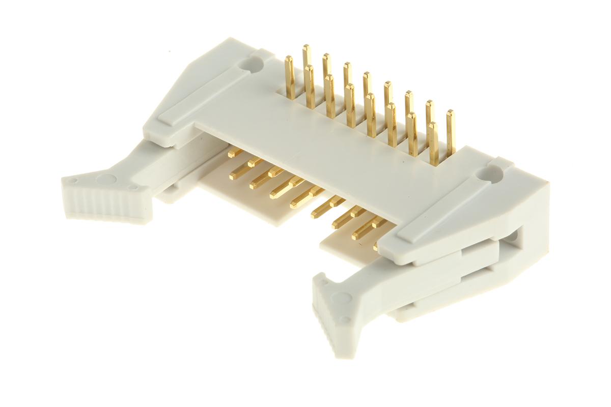
PCB (printed circuit board) headers are connectors that allow you to join PCBs to other wires and boards using a single block. Typically, these headers have a surface designed to be soldered onto the board, with the other side of the header allowing external connections. Depending on the type, the header can have a shroud to make the unit and connection more secure.
You’ll find PCB headers on almost every circuit board, as they make connections easy. It’s just a single block, but it allows multiple connections. This makes the connectors quite popular in dev kits like Arduino and Raspberry Pi, as well as products made with reboard boards.
The type mostly varies based on the header structure and pin design.
Here are the most common ones you’ll run into.
Single Row vs. Double Row Headers
Most headers will have a single or a double row of pins. The single-row ones are easier to solder to the board, and they work well when you only need a few connections. The double-row ones will give you more flexibility, especially if you may need to expand the connections later.
Machine-Pin Headers
These have round pins, instead of the more common square ones. The shape allows them to mate more securely, and it also allows repeated insertions without compromising reliability. They generally offer better electrical connections and have a longer lifespan.
Angled Connectors
When you don’t have enough vertical room, you can use angled connectors to maximise the space. Most of these have a 90° or 180° angle.
Note that all the above can be shrouded or non-shrouded. The shrouded ones have a plastic casing that holds the connections in place and protects the pins from bending, but they take up more space compared to the non-shrouded ones.
What to Consider When Choosing PCB Headers
You’ll need to look at more than just the pin count. When you consider the header as part of a larger circuit, you’ll be in a better position to ensure a reliable connection.
Pitch and Spacing
Different PCB headers have different distances between the pins, known as the pitch. When you go for a smaller pitch like 0.44 mm, you’ll save board space and have a cleaner connection.
However, there’s a trade-off in the soldering process. Since the pins are quite close to each other, you’ll need to be steadier and have precise equipment. You can’t bridge the connections.
A larger pitch, like 47 mm, will be easier to handle, but it will take up a good chunk of your board space. Think about whether your priority is space or efficiency, as well as what the task requires. You can then balance the size with ease of use. Ensure you are comfortable working with the pitch you choose.
Electrical Ratings
Every header comes with a maximum current and voltage rating, and different tasks have varied power ratings. A motor controller will need more power than a PCB header used for simple data signals. If you use a smaller rating in power circuits, you’ll end up with excessive heat, signal loss, or premature failures. So, you need to match the rating with the use.
To ensure you don’t assume or use the wrong rating, always check the datasheet, then compare it with your load requirements. Even if you are working with low-power designs, don’t mismatch them, as you may end up with reliability issues down the line.
Mechanical Strength
Different PCB header designs make the connector suited for different purposes. Some, like the connectors used in consumer electronics, only need to be inserted once. They won’t undergo much strain and will stay in place, so a simple PCB header will work well.
However, if it’s a development kit, you’ll need a PCB header that can handle more wear. They’ll need to be plugged and unplugged, and you can also bend the pins during assembly and repairs. Other connectors, such as PCB headers used in automotive and industrial systems, will need to withstand vibrations and frequent maintenance.
In such cases, you need machine-pin headers and shrouded versions.
Orientation and Layout
As we’ve already seen, PCB headers come in vertical and angled versions. Your choice here should depend on the size of the enclosure or the space available, and the cable routing.
Using angled headers is recommended when working with tight spaces as they save a lot of vertical space. They are also more suitable when you need to mount a connector near enclosure walls.
On the other hand, vertical headers are quite efficient when you don’t have space or access issues. They are much easier and faster to work with.
Compliance and Safety Standards
The UK is quite strict on compliance, and it should be part of your PCB header selection from the start. Like all other electronic components, these headers need to meet standards like the UKCA (UK Conformity Assessed), which is equivalent to the EU’s CE mark.
There are also the RoHS regulations (Restriction of Hazardous Substances) related to harmful materials and possibly the BS EN 62368, which covers electrical safety in IT and audio/video equipment.
Environment and Application
Different boards are normally subjected to different environmental conditions. If it’s used in an outdoor environment, it will be exposed to moisture, dust, and temperature swings, most of which don’t apply to boards used in desktop devices.
If the PCB header will be exposed to harsh conditions, ensure it is shrouded, as this will give it significant extra protection.
Best Practices for Soldering and Mounting PCB Headers
After choosing the right header, you still need to ensure it’s properly installed.
Here are a few tips to help during the process:
Align the PCB header before you start soldering. You can use a jig to hold the header straight.
The plastic can melt and loosen the pins, so use the right amount of heat and precise tools. You should also keep the top of the iron clean and use flux to ensure there’s proper flow.
Watch out for bridges, especially if your PCB header has a small pitch. Double-check after the process.
If the board will be exposed to vibrations or frequent handling, reinforce the PCB header. You can use a small amount of epoxy or hot glue after soldering, as these won’t affect your connections.
Consider how cables will connect before soldering your header, as you should leave enough space for cables.
Following these will ensure that on top of choosing the right PCB header, your connection is reliable. It will also make assembly, testing, and servicing much smoother.
Recycling car batteries helps protect our environment. It also supports sustainability. Knowing how to recycle car batteries safely is important for everyone. The impact of…
Managing storage on an Android device can be tough, especially with different apps that have their own rules for deleted files. Android doesn’t have a…
We use cookies on our website to give you the most relevant experience by remembering your preferences and repeat visits. By clicking “Accept”, you consent to the use of ALL the cookies.
This website uses cookies to improve your experience while you navigate through the website. Out of these cookies, the cookies that are categorized as necessary are stored on your browser as they are essential for the working of basic functionalities of the website. We also use third-party cookies that help us analyze and understand how you use this website. These cookies will be stored in your browser only with your consent. You also have the option to opt-out of these cookies. But opting out of some of these cookies may have an effect on your browsing experience.
Necessary cookies are absolutely essential for the website to function properly. This category only includes cookies that ensures basic functionalities and security features of the website. These cookies do not store any personal information.
Any cookies that may not be particularly necessary for the website to function and is used specifically to collect user personal data via analytics, ads, other embedded contents are termed as non-necessary cookies. It is mandatory to procure user consent prior to running these cookies on your website.
We use cookies to ensure that we give you the best experience on our website. If you continue to use this site we will assume that you are happy with it.